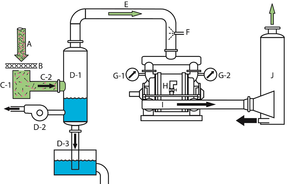
Vacuum pump systems are used for dewatering saturated materials, filtering liquid from slurries, evaporative drying or pneumatic conveying. These types of vacuum systems are used in paper making, food processing, steam turbine power and chemical manufacturing. Image 1 shows the lettered components of a vacuum system referenced in this article. All units in this article are given as Imperial.
The natural force of gas pressure are the velocities of the gas molecules, known as the kinetic energy of gas. Gas pressure is caused by molecules of gases darting at high velocities in random directions. They hit the walls of a vessel to cause an internal pressure but can also shoot through a medium containing water or solids in a slurry and then fill the inlet flange of a vacuum pump.
of Vooner FloGard Corporation)
Vacuum pumps do not pull gas. The source force of inlet air (A) in open vacuum systems is local atmospheric air converted to standard conditions of 14.7 pounds per square inch absolute (psia) at sea level, known as standard cubic feet per minute (SCFM) at atmospheric pressure.
Closed systems typically have the inlet gas as a vacuum, which can be converted to standard conditions. The measured pressure (or vacuum) of a vacuum system is also based on the weight of a square area column of air 250 miles tall—weighing 14.7 pounds per square inch (psi). An equivalent 1 square inch column of mercury (Hg) weighing 14.7 pounds at sea level is 29.92 inches tall and referred to as inches of Hg absolute, or the standard absolute pressure (psia or Hg pressure abs).
The work of a vacuum pump system is usually through a medium (B) to dewater a wet medium, make filter cake, pneumatically move materials in a pipe to a collection vessel or other industrial separation of materials with the use of air flow moved by differential pressure.
The vacuum system developed vacuum is in the vacuum box (C-1) where the pump collects gas faster than the atmospheric pressure gas can enter the box through a restricted opening of the vacuum box. The box or vacuum chamber is considered the “heart” of the system.
The pipe connecting the vacuum box to the vacuum pump system will carry air and a mixture of solids such as water or other process suspended solids. With this mixture, the pipe diameter at (C-2) should be chosen for a maximum air flow of 3,000 feet per minute. Ensure there are no U-shaped loops in the pipeline to trap/hold water. Remember that inlet atmospheric air pressure is the force pushing this process air to the vacuum pump.
A vacuum pump is designed to be a dry gas positive displacement mover of gas. Any water traveling in pipe C-2 needs to be separated in inlet gas water separator (D-1). The air water mixture enters the separator and by gravity goes to the bottom of the separator as the air is pushed out the top. Since the inlet separator operated under vacuum, the water must leave the separator by either an unloader pump (D-2) or a barometric drop leg (D-3).
The pipe from the inlet separator to the vacuum pump (E) is filled with the
volume of actual cubic feet per minute (ACFM) at the vacuum level developed in the vacuum box. With the pipe filled with mostly air, the diameter of E should be chosen for a maximum air flow of 5,500 feet per minute (ft/min).
The inlet gas is possibly partially saturated with water vapor. When the temperature of the inlet saturated gas temperature is more than 15 F higher than the seal water temperature, and the vacuum level is lower than the vapor pressure of the saturated gas, then spraying a portion of the seal water into the inlet pipe to the pump at F will condense an amount of the vapor and will reduce the volume of gas to be pushed through the vacuum pump.
A vacuum pump is a positive displacement device of a constant volume of gas per time. By that definition, this device is a compressor of gas with interest in the inlet flange. There is no word in any language for the opposite of a compressor, so engineers say “vacuum pump.” The vanes on a rotor are the walls of the compressor cylinders and a ring of water provides the pistons in the cylinders.
A key to the operation of the vacuum pump is the flow of seal water through the pump. The common question is, “how much seal water flow do I need?” The best answer is, “enough to establish the maximum stable vacuum.” In other words, too little will show fluctuations in vacuum level, and too much will simply push the excess water out the discharge port without increasing the vacuum level, but unnecessarily consume extra power.

The globe linear regulating valve (H) needs to have linear flow control sensitivity with proportional relationship between valve opening and flow rate. Pipe diameter should be selected for the maximum seal water flow rate given by the pump manufacturer. Over years of service, the amount of seal water will need to be increased to compensate for pump material and dimensional losses in the seal section of the pump.
After a long time, when the amount of seal water flow is known, the linear flow control valve can be replaced with a differential flow meter (DFM), which measures fluid flow through pipes. The elements of a DFM are a circular metal disk with a specific hole diameter that reduces the fluid flow in a pipe.
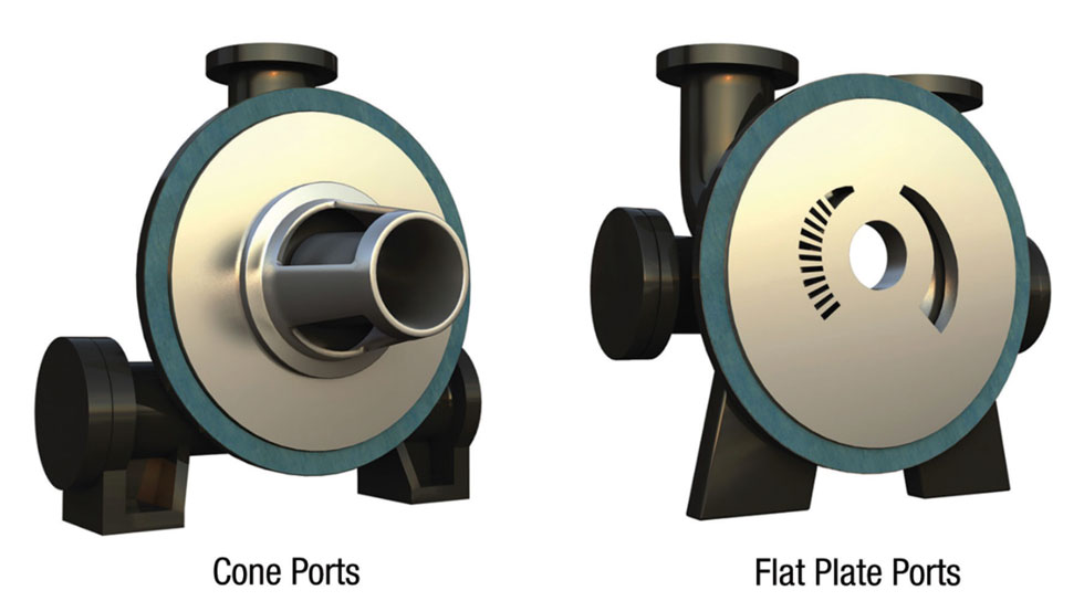
The design of single-stage vacuum pumps can be differentiated by the inside design of the inlet and discharge ports in relation to the rotor of vanes. Image 2 shows the basic different designs of the cone port and flat plate port design.
Cone port, with larger port areas, can pass solids including water through the pump easily and are more efficient for vacuum applications lower than 24 inches of Hg. The cone port design can condense warm saturated gases and easily pass the resulting droplets of water.
The flat plate, with smaller port areas, are designed for clean gases such as in the chemical industry and are more efficient in vacuum applications higher than 24 inches of Hg.
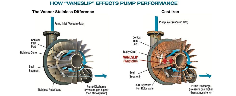
Both cone port and flat-plate port pumps have a common design feature with the internal seal segment separating the high-pressure discharge gas from getting into the low-pressure (vacuum) segment of the pumps. This wasteful flow of high-pressure gas is called vane slip, shown in Image 3. Control of vane slip can be more efficient with stainless steel than with cast iron pumps. The seal segment for the flat-plate design is in the 12 o’clock position also between the end of the discharge port (see Image 2, shown left side, and the beginning of the inlet port, shown right side).
The choice of vacuum pump metallurgy for durability is key in the consideration of product total cost of ownership (TCO). Vacuum pumps use water as the working piston in the cast iron vacuum pumps. The usual result of water and cast iron is the formation of destructive iron oxide (rust).
Iron vacuum pumps, with use, lose their internal critical dimensions and consequential loss of airflow at vacuum. This reduces process production. If this leads to short pump life, the TCO is high and unavoidable.
Image 3 shows the difference in stainless steel and cast iron rotor cone combinations at the important seal segment and the development of vane slip. The surface loss of iron could be 30 percent in 10 years.
If iron oxide (rust) removes iron form the critical clearance in the seal segment, then high pressure discharge gas “slips” under the rotor vanes and enters the inlet segment, rather than exiting the discharge port. This unwanted gas entering the inlet segment robs space for new vacuum air to enter the pump. This is a loss of process vacuum air entering the vacuum pump and a loss of vacuum process production.
Stainless steel may prevent vane slip by the continual formation of dynamically hardened chromic oxide from water and materials rubbing the surface of the stainless. This constant rubbing can cause dynamic hardening of chromic oxide in the stainless steel.
The surface loss for stainless would be in the range of 10 percent over 20 years. Stainless steel has a constant low thousandth of an inch (mils) per year loss of surface material and retains the critical rotor cone clearance in the seal segment and process production.
Since the vacuum pump discharge pipe from the pump (H) to the discharge separator (J) carries a combination of pump discharge air and seal water, the diameter would be sized for less than 3,000 feet per minute. Since the vacuum pump will not tolerate back pressure, the discharge manifold and discharge pipe centerline should be level or below the center of the inlet flange of the discharge separator.
The discharge gas and seal water separator open to the atmosphere separator is not considered a pressure vessel since it discharges to the atmosphere. The gravity drain is considered open and should not have any pipe attached that causes back pressure.