Corrosion can disable pipes and cause catastrophic failures. In the petroleum and chemical industries, proactive monitoring and inspection of mission-critical pipes are required to look for signs of corrosion. This article highlights two key questions that can help users correctly diagnose this type of wear.
1. Is My Part Made of the Right Material?
Remember that material mix-ups can happen at the component manufacturer, on delivery, during stocking or restocking, or on installation. The wrong material can corrode at an accelerated or unpredictable rate, increasing the operational risk at chemical or petroleum facilities.
While proper labeling and material test reports (MTRs) can help prevent these mix-ups, they continue to happen and can lead to catastrophic incidents. Major incidents at oil and gas facilities are frequently attributed to accelerated corrosion due to incorrect material installations.
Handheld XRF Analyzers
Inspectors can use X-ray fluorescence (XRF) tools to quickly and nondestructively verify material composition. Positive material identification (PMI) using portable XRF analyzers is standard practice for critical applications, where inspectors can identify common alloys in a few seconds. The handheld design also enables inspectors to test fittings and pipes prior to installation or while they are installed and active.
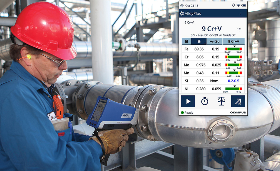
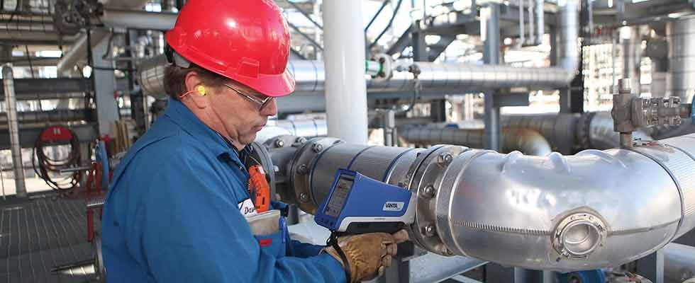
IMAGE 1: Diagnosing corrosion on a pipe (Images courtesy of Olympus)
Grade identification with XRF is determined by comparing elemental results to a library (typically more than 500 grades) of known grade specifications. Modern XRF analyzers can clearly display the concentration of elements detected and how they compare to the matched grade. Users can then see if the grade installed is the one specified in the facility’s piping design.
Handheld XRF can also detect corrosion susceptibility. For instance, XRF can diagnose susceptibility to sulfidic corrosion via silicon concentration; hydrofluoric acid (HF) alkylation via chromium (Cr), nickel (Ni), and copper (Cu) concentration; and flow accelerated corrosion via low Cr concentration. Knowing these risk factors can help save time and money by signaling when and where to schedule maintenance.
Corrosion Analysis With XRD
While XRF provides elemental composition, it cannot identify compounds. For example, XRF says if the products causing corrosion are iron (Fe) based, but it cannot distinguish between the types of iron oxide corrosion products (e.g., FeO, Fe2O3, and Fe3O4).
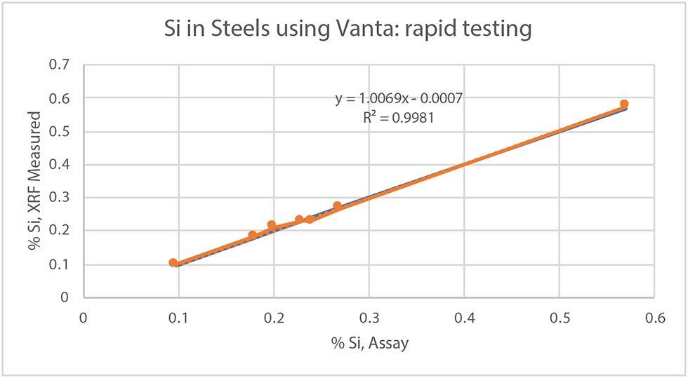
IMAGE 2: A handheld XRF analyzer can detect silicon (Si) in steels—an indicator of corrosion.
Determining phase compositions is vital to understanding the corrosion process since different corrosion minerals occur in varying environments and conditions. This information can be obtained through another technology and that is X-ray diffraction (XRD).
XRD is a commonly used technique for corrosion analysis since it generates data on the phase/crystallographic content. Phase identification can help locate the root causes of corrosion in industrial facilities and offer solutions to treat and prevent it. Rust, ferrous and lime scaling buildup corrosion are just a few corrosion species analyzed with XRD.
Combining XRD & XRF
Combining XRD and XRF technologies can help users understand corrosion events. First, XRF provides quantitative elemental analysis of the various corrosion areas. Then the same aliquot of sample is transferred to the XRD instrument, which identifies the compounds/phases and provides a quantitative ratio of these compounds.
Portable XRD and XRF analyzers can deliver this information on-site.
2. Is My Material Mechanically Sound?
Corrosion can still occur even if a part is made of the right material. For this reason, it is important to answer question No. 2: Is my material mechanically sound?
Corrosion is one of the most common defects monitored by mechanical integrity groups of asset owners/operators. It often begins in an area of the asset with a minor manufacturing defect or in a location with mechanical damage, enabling higher concentrations of corrosion catalysts to linger. While its presence does not necessarily indicate immediate danger, the presence and severity of corrosion must be monitored to check if a part is mechanically sound enough to operate safely.
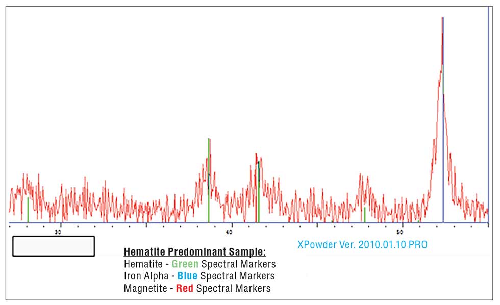
IMAGE 3: Hematite sample
Ultrasonic Thickness Gauges
One way to determine if the material is mechanically sound is through nondestructive ultrasonic testing methods. Ultrasonic thickness gauging is a common method of corrosion detection and quantitative evaluation.
In ultrasonic thickness gauging, a rugged, handheld instrument connects to an ultrasonic transducer, which converts electrical pulses into sound waves typically between 1 and 10 megahertz (MHz) in frequency (well above the human hearing threshold).
The user places the transducer on a pipe’s outside surface, and sound waves travel through the thickness of the pipe wall. They reflect from the inside of the pipe, and the instrument uses a simple formula to convert the transit time of the wave’s round trip through the pipe wall into a precise thickness measurement.
This process is a simple, effective method to measure the amount of remaining wall present at a particular location on an asset.
When corrosion is present in a component, it reduces the thickness of the part in specific locations. Asset owners intelligently select many (sometimes thousands) of locations to monitor for variation in material thickness, often called condition monitoring locations (CMLs).
Nondestructive testing (NDT) inspectors record periodic thickness measurements at each CML. Over the asset’s life, huge databases of CML thickness values are updated and trended after each inspection. Specialized software uses this data and other factors to evaluate a component’s risk of failure.