The Background
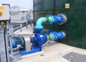
Two 11-stage BB5 pumps of 50 kilowatt (kW) rating—running at 60 Hertz (Hz) and 3,575 revolutions per minute (rpm)—were commissioned on a 2 x 100 percent configuration to naphtha (specific gravity of 0.685 and viscosity of 0.4). The pumps were designed to deliver 21.2 cubic meters/hour (m3/hr) at a differential pressure of 35.4 bar (527 meters of head). The pumps failed repeatedly with similar symptoms.
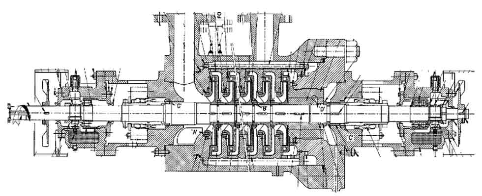
IMAGE 1: Naphtha pump with five of the 11 stages shown. (Images courtesy of Saudi Aramco)
Observations & Findings
Upon commissioning, there was an initial observation of variation in balance-line pressure caused by repeated popping of the pressure relief valve on the balance line. The manufacturer recommended that the pressure relieve valve setting on the balance line be increased from 5 bar to 8.5 bar to resolve this issue. However, the vibration levels were high and gradually increased until the pump failed. The pump was dismantled, and a standby pump was started, which failed again with identical symptoms. The pumps were dismantled and both showed severe and similar internal rub damage (Images 2 to 4).
Due to the low power rating of 50 kW, there was no embedded instrumentation for continuous monitoring of vibration signals. All vibration was measured by seismic handheld equipment. The pumps were reassembled with a mix of refurbished and new parts meeting clearance and assembly requirements of the manufacturer and put back in service. Both pumps failed with the same symptoms. A root cause analysis was initiated, and pump manufacturing, testing and commissioned data were evaluated.
Pump Design
With a 55-millimeter (mm) shaft distance between bearings of 1,410 mm, this gave the L3/D4 factor (the stiffness ratio or flexibility factor) of 306. The pump is a back-to-back design—that is, there is no shaft support between impellers. The data sheet did not show a calculation of first critical speed.
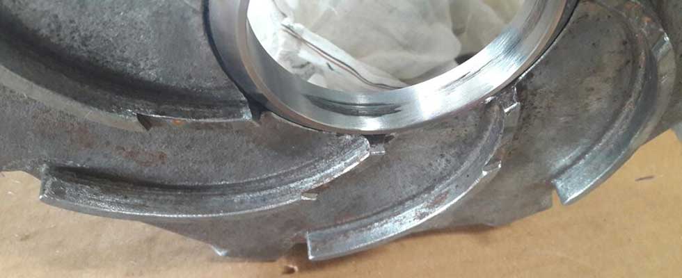
IMAGE 2: Wear on casing wear rings
A hand calculation indicated that the pump rotor may have a natural frequency close to running speed.
The pump had an “external balance line”—the low pressure side of the balance sleeve was not directed back to the suction of the pump; instead it was routed back to the naphtha storage tank through minimum flow pipe.
Pump Factory Test Deficiencies
The pump was tested for performance at the manufacturer’s factory in December 2014 and witnessed by a third party. Evaluation of the pump test data indicated that the pump was tested at 50 Hz (2,950 rpm), and never tested at the rated speed of 3,575 rpm. The “external balance line” flow measured during testing was 6 m3/hr instead of the expected 1 m3/hr. The higher-than-expected pump efficiency masked the high balance line flow.
Pump Site Deficiencies
There was no provision of air bleed on the pump suction piping. The only air bleed was on pump casing.
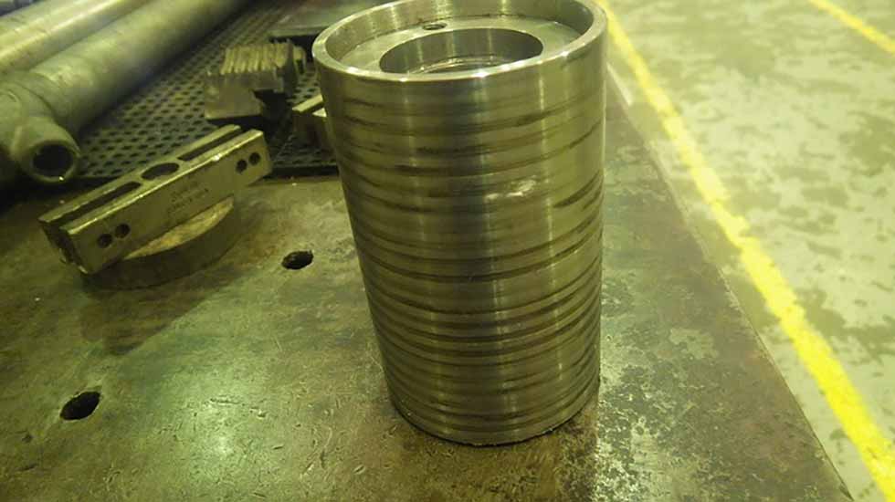
IMAGE 3: Wear marks on balance drum
The pump was 300 meters away from the tank, and the suction piping was not insulated. Residence time of naphtha in the 10-inch pipeline at rated flow rate was estimated at 10 minutes, which is significant in Saudi Arabian summers when ambient temperatures can approach 50 C (122 F). The pump could have operated with lower density and viscosity and higher vapor pressure than design conditions.
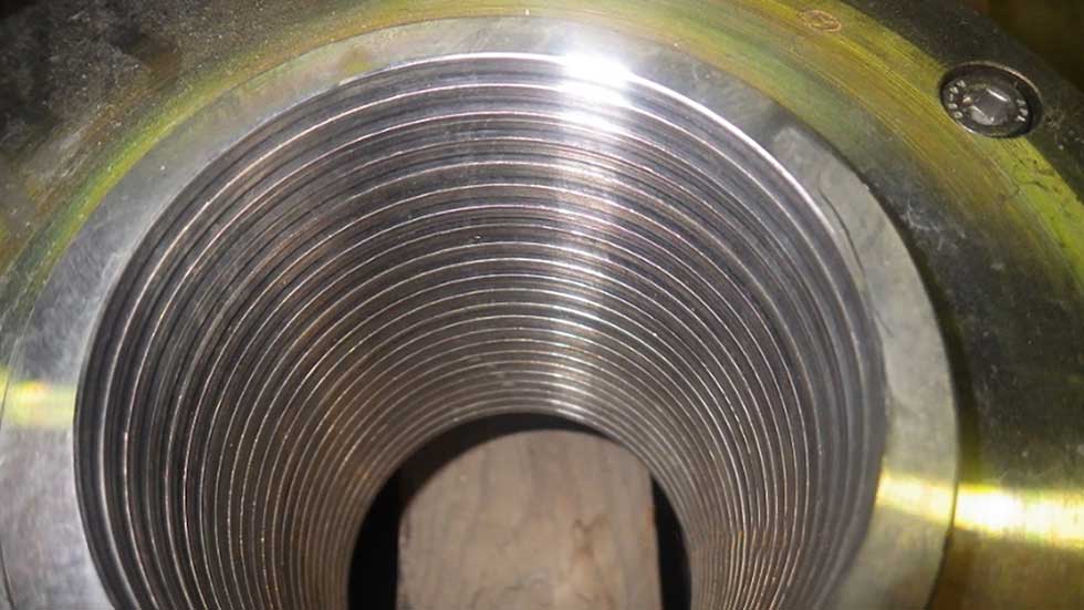
IMAGE 4: Balance sleeve serrations
Inspection of Damaged Rotor
All the as-found clearances were tabulated and the depth of damage was determined. Results indicated that the rotor may have deformed per a shape typical of first mode of rotor resonance. Both of the bearings were cooled by one shaft-mounted bronze fan on each side. The brass fan weight was 1 1/2 times the weight of the impeller, consequently impacting the natural frequency of the rotor.
IMAGE 5: Impact test results
Rotor Bump Test
The rotor was reassembled and a bump test was carried out; the results are noted in Image 5.
Probable Root Cause
There are three options for the likely root cause of the failures:
- There is a strong possibility of resonance.
- It is possible there is some other type of rotor dynamic instability due to the flexible shaft, as well as high swirl-induced instability and insufficient Lomakin support.
- The net positive suction head (NPSH) may be limited due to the naphtha temperature being higher than the design.
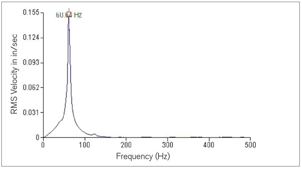
IMAGE 6: Shaft first natural frequency
Corrective Actions
The following are suggestions to correct these possible issues:
- Increase the shaft diameter to the maximum possible diameter without impacting the pump hydraulic performance and mechanical integrity. Raise shaft diameters under impellers by 5 mm and at mechanical sleeve IT from 40 to 41 mm.
- Provide radial slots in balance bushing high pressure side ensuring swirl-free leakage flow to improve rotor dynamic stability.
- Replace the bronze bearing fans with aluminum fans.
- Increase stiffness and provide better support to the rotor by reducing clearances to 70 percent of American Petroleum Institute (API) clearance.
- Make all close clearances pairs to have flat-on-flat surfaces to increase Lomakin support.
- Use nonmetallic, polyetheretherketone (PEEK) wear rings and balance bushing.
- Machine 5.4 mm unused coupling hub diameter to further reduce overhung weight by 1 kilogram (kg).
- Manufacturer to conduct rotor dynamic analysis per API 610 for the original, as well as the modified, rotor.
All corrective actions were implemented, the pumps were restarted in August 2017 and have run trouble-free to date.