When troubleshooting pump performance problems in the field, I often encounter issues because the pump operator doesn’t realize the pump pressure gauge only measures static pressure in the pipe. And your reply would be: well, yes of course, isn’t that what they are supposed to do? I would counter that the gauge is actually only measuring one of three things that are going on in that dynamic system.
This month’s column is about the other two energy forces going on inside the pipe. The gauge or pressure transducer, through no fault of its design, can only measure pressure, which is a simple force divided by the surface area (pressure = force ÷ area); but there are two other factors present: the head energy due to the liquid’s velocity (kinetic energy) and the potential energy due to the elevation change, if applicable.
Again, there are three dynamic factors we are concerned with inside the pipe of a dynamic system (dynamic simply means the liquid is flowing):
- there is the force of static pressure
- there is the head (kinetic energy) due to the velocity of the liquid
- there is the head (potential energy) due to an elevation change above the reference datum
Most often, the datum reference is the impeller centerline, and if there are no elevation changes between the pump and the measurement point, then the factor approaches zero and drops out.
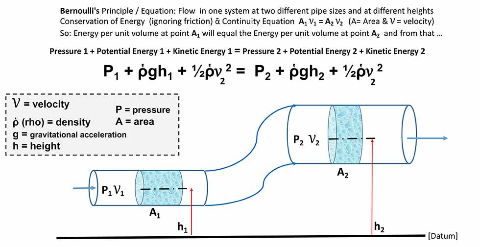
Many readers may already recognize these three factors as the main components in Bernoulli’s equation. This equation is useful to explain the lift afforded by the wing of an airplane, the loft of a golf ball or the deceptive curve of a baseball closing at 100 miles per hour (mph) toward home plate. For calculating what will happen in a piping system the equation is priceless.
Pump Performance Ratings
Centrifugal pump performance is measured in units of both flow rate and head (dynamic head or total head). In United States Customary Units (USCS), we use the units of feet or in the International System of Units (SI) we use meters. Published performance curves for most all pump manufacturers do not rate the pumps in pressure, they rate the pumps in head.
Note: Some manufacturers do publish curves in pressure for simplistic reasons based on common application assumptions, for example, a well pump for domestic water use.
Pump manufacturers publish pump performance curves in units of head—total dynamic head (TDH) or total head (TD)—for many reasons, but the most common is they do not know the specific gravity of the fluid that will be pumped. Even if you were pumping pure water, the performance as measured on a pressure gauge would technically change with every degree of temperature change, because temperature changes the specific gravity of the liquid. By publishing the curves in units of head they can publish one curve regardless of the liquid, the temperature and the specific gravity. When manufacturers state units of head, they are enacting an energy term and the confusion is because we are accustomed to use units of feet or meters only for distance. The reasons for this ill-fated and confusing word choice of “head” will be the subject of another column. Hint: think of height as a distance.
Note: Centrifugal pump manufacturers also assume the pumped fluid is single phase, Newtonian and the viscosity at the pumping temperature is lower than a nominal 10 centipoise (cP)—surely no more than 40 cP—otherwise the curve must be viscosity corrected. In the pump industry, it is assumed that all pump performance curves are based on pumping water at around 65 F unless otherwise stated.
1. Musketeer No. 1
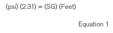
Pressure is not head, but there is a relationship. See Equation 1 to better understand the relationship of head to pressure. Where SG stands for specific gravity and 2.31 is the relationship of the height of a column of water to the corresponding pressure.
That is, a column of 65 F water that is 2.31 feet high will exhibit a pressure of 1 pound per square inch gauge (psig) at the bottom of the column.
When the pump performance is recorded for the published curves, the manufacturer is looking solely at what is happening between the pump suction and discharge flanges and, because of the laws of the conservation of energy, we can calculate what will happen downstream. Refer to Hydraulic Institute/American National Standards Institute (ANSI) specifications 14.6-2011 for details. The pump manufacturer publishes their performance curve based on units of head and flow in terms of total energy, not pressure. Also, they don’t know your system’s arrangement, nor are they responsible for the system curve. Remember from previous columns that the pump will operate where the system curve dictates if it is capable of operating at that point.
Real World Issues
Let’s come back to the original issue of the customer’s system and the pump that is allegedly not operating correctly. The pump has an upstream suction side supply system and downstream the fluid has a job to do whether it is simple liquid transfer, boiler feed, hydraulics, a chemical process reactor, thermodynamic heat transfer or 100 other typical applications.
In the geometry of that system, there is piping of different sizes, valves, various components and normally there are also elevation changes. Using Bernoulli’s equation, we can predict the pressure (head) anywhere in the system. Just for now, please realize that the typical discharge gauge is simply measuring static pressure at some location, which again is a force per unit area, not an energy level. The gauge visually communicates the pressure, but it is not reading the head due to the liquid’s velocity (kinetic energy), which is a component of the total energy the pump has converted. The gauge also does not tell you that the elevation has changed (potential energy)—at least not in a direct fashion, unless you already know to calculate and compensate.
The operator subsequently looks at the pump curve for expected head values or for the expected pressure to read from a gauge. He/she then completes the head to pressure conversion or vice versa and determines that the pump does not meet the criteria.
The operator then calls the pump supplier and confidently states the pump is not operating properly, it is not on the curve and is off on flow or head or both. The issue is that the operator is not adding the head due to the liquid’s velocity.
2. Musketeer No. 2
Some 10 years ago at a Midwestern paper mill, I was summoned to determine the issue with a newly purchased replacement pump that was not making the expected pressure. I looked over the pump, the system and the respective curves for each. I determined the pump performance was exactly where it was supposed to be. The discharge pressure gauge had been moved out and up from the pit where the pump was located to an easier-to-read and safer location on the main level walkway at an elevation nearly 50 feet above the pump.
When I added the 22 psi (50 feet) loss due to the change in elevation to the pump performance, the pump was on the curve and doing just fine. The gauge was correctly reading the static pressure and it was also showing the elevation change of 50 feet (by reading a pressure of 22 psi less than at the pump), but the operator did not correct the gauge reading for the change in height. The gauge was also not reading the velocity head (kinetic energy), which in this case was negligible.
3. Musketeer No. 3
Here is the real reason for this month’s column. A recent issue at a manufacturing plant involved a pump that allegedly was not performing correctly. The variable speed pump was not making pressure on the right half of the curve. I requested photos of the installation and noticed that the pump discharge gauge was directly on the 2-inch discharge flange. The flow rate was purported as close to 950 gallons per minute (gpm), but the expected pressure was markedly off. First, I calculated the velocity head of 950 gpm through 2-inch pipe. The liquid velocity for 2-inch steel pipe based on the Darcy-Weisbach formula is around 97 feet per second (ft./sec.).
Using the liquid velocity of 97 ft./sec., I calculated the velocity head at 146 feet (Equation 3). Adding the 146 feet of head due to the velocity that is not measured by the gauge to the amount displayed from the gauge (gauge pressure of X was converted to head), we then had the correct amount and the pump was within tolerance of the published curve. Note the gauge elevation difference was only about 1.5 feet (0.65 psi) and so was negligible.
Why Is This Important?
If you are in the plant looking at a potentially troublesome pump on ambient water service, and you read the suction and discharge pressure gauges to get a differential pressure of, say, 100 psig, you would then convert the 100 psig to head (100 x 2.31 = 231 feet of head). You then look at the manufacturer’s curve and look up 231 feet for the impeller diameter and speed of your pump. From this coordinate point, you drop directly down at a right angle to the X (horizontal) axis of the curve and pick up a flow rate. If you did not add the velocity head component to your head total, and/or if you did not allow for the gauge position elevation changes, then the head data point, and consequently the flow rate point, will be wrong. As an antithesis example, if you read a presumed accurate flow rate from the flow meter and looked up the expected head value on the curve, it would not match the differential pressure from the gauges (converted to head).
Most of the time, if the system is designed correctly and the instruments are located properly, these two additional components of velocity head and elevation head rarely come into play and/or the contributing amount is negligible. But I also know that the three musketeers are always present in the background.
Les Trois Mousquetaires
Why did I bring up the three musketeers?
If you remember the book and/or the movies, the mantra for the musketeers was “one for all and all for one.” I use this mnemonic device to remind me that when I am troubleshooting a system, there are really three characters at play inside that pipe. I can often read the pressure from the gauge, but I also must account for velocity head and elevation. Wherever Athos is present there is also Porthos and Aramis—Les Trois Mousquetaires—with apologies
to d’Artagnan.
Tech Support Tips
If you know the flow rate and the pipe size, you can look up the liquid velocity in reference books such as “Cameron Hydraulic Data” or Crane’s Technical Paper 410. There are also numerous websites, but not all sites are accurate. If the chart does not cover your flow rate for the pipe size, that is a red flag and you can be fairly sure the velocity head is very high.
For example, look up 950 gpm in a 2-inch steel pipe. Most charts of 2-inch pipe stop at 300 gpm because higher flow rates/velocities are not normally recommended in a pipeline. Conversely, realize that it is acceptable as a pump discharge nozzle velocity due to the very short span involved.
Note: For the gauge to be more accurate, it should be placed downstream of the pump in an area of lower velocity in a larger pipe diameter.
If the flow rate is not on the chart, use Equation 2.
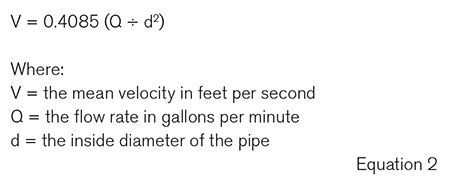
If you want to calculate the velocity (mean velocity) of the liquid in the pipe, you can also use a simple formula, which I will not derive, but the end result is shown in Equation 2.
Once you know the liquid velocity in the pipe it is then a simple calculation to figure out the velocity head (hvelocity). The formula for the velocity head is shown in Equation 3.
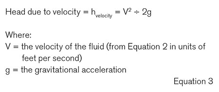
Typically, you can use 32.2 feet per second squared for the acceleration of gravity, unless you are working on pumps for rocket engines at NASA, SpaceX or extraterrestrial applications.
Bernoulli’s equation would take another six columns—or maybe more—to explain, but I will post a simple version here for completing the story (Image 1).
References
Also read the Pumps & Systems articles written by Joe Evans (“The Bernoulli Principle” and “Understanding Velocity Head”) and the two-part article by Lev Nelik: “How Important Is Accounting for Velocity Head and Gauge Elevation?”