During the commissioning and startup of an alumina processing plant in the Middle East, a significant recurring pump issue was causing delays to the commissioning of the facility. When de-energizing the equipment, the live steam condensate vertical can pumps experienced repeated failures of all installed units. These seizures occurred at both the design fluid temperature and when pumping cold water.
Because this was a new plant in the commissioning phase, the equipment was under warranty. However, negotiations with the OEM were lengthening the challenged startup schedule. There was little insight into the root cause of the equipment failure.
As the repeated failures were affecting the plant commissioning date, the large architect, engineering and construction (AEC) firm in charge of plant commissioning decided to contact an independent, aftermarket service provider located in Dubai, United Arab Emirates, to conduct an assessment to determine the root cause of the pump failures and provide solutions.
Investigating problems for equipment under warranty can be an arduous process. While the end user prioritizes a swift return of service for equipment and assurance of future reliable operation, they can be met with a reluctance to discuss possible design flaws during warranty claims, depending on the OEM.
Some AECs and end users do not have the internal capabilities that allow an in-depth analysis of equipment design and operation. These situations can lead to the use of an unbiased third party.
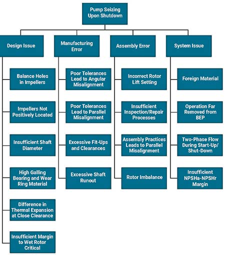
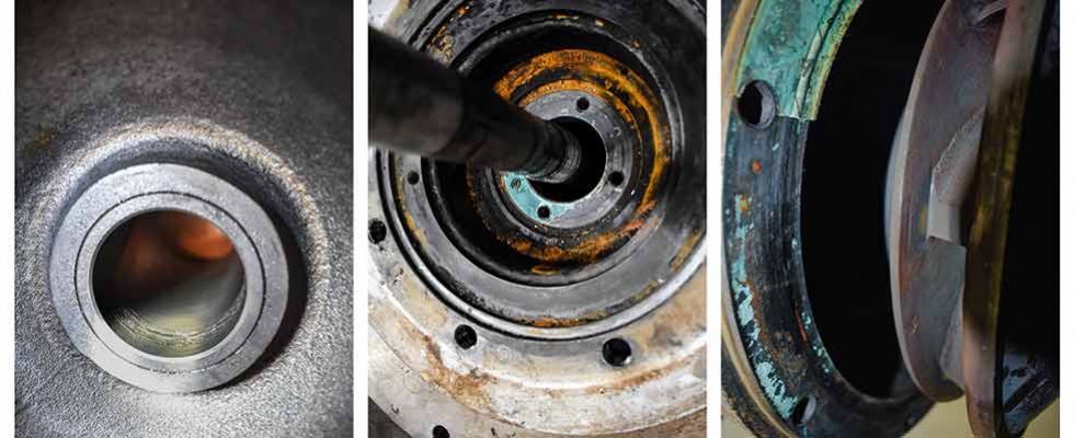
IMAGE 1: The in-depth flowchart details possible failure mechanisms based on various factors including design, manufacturing, repair and more. (Images courtesy of Hydro, Inc.)
The Investigation Methodology
A detailed flowchart was developed by the independent service provider detailing the possible failure mechanisms that could cause pump seizure during shutdown (Image 1).
This flowchart was organized based on causal factors including design, manufacturing, repair, assembly, installation and system influences. An exhaustive list of contributing factors, ranging from design and assembly to on-site operation and maintenance, were included in the assessment.
The possible failure mechanisms were then entered into a Support-Refute Matrix wherein site data, design calculations and inspection findings were used to evaluate the possible failure mechanism as either probable cause, influencing cause or no cause.
The installed pump design was also compared to traditional vertical can configurations that have experienced reliable service in the live steam condensate application.
Ultimately, one of the failed pumps was disassembled and inspected. Each of the possible mechanisms identified as a probable or influencing cause was validated or refuted through analysis or inspection data.
Inspection & Evaluation Findings
The analysis showed that several design choices affected the reliability of the equipment. One of these was the guide bearing material selection. The type 410 chrome steel selected for this particular installation has a propensity for galling.
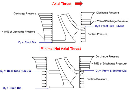
IMAGE 2: Balanced impellers are subject to suction and discharge pressure on either side of the impeller, resulting in a net zero axial thrust.
Almost all condensate pumps have either bronze or carbon graphite bearings because of the material lubricity required when handling high purity liquid. A high galling material, such as 410 chrome steel, will “grab” the shaft when contact is made and increase the possibility of seizure.
Other contributing causes added to the susceptibility of the pump to seizure, including increasing the likelihood of contact within the close clearance guide bearings. The significant influencing factor was the use of a balanced impeller design.
Balanced impellers include front and back wear rings with holes drilled through the eye area of the impeller to provide pressure equalization on the impeller shrouds (Image 2). This design concept limits the hydraulic downthrust, enabling the use of a smaller motor thrust bearing.
For this application, a large suction pressure results from pumping 152 C to 196 C (306 F to 385 F) condensate. In this situation, reducing the hydraulic downthrust by using a balanced impeller design can result in an upthrust scenario.
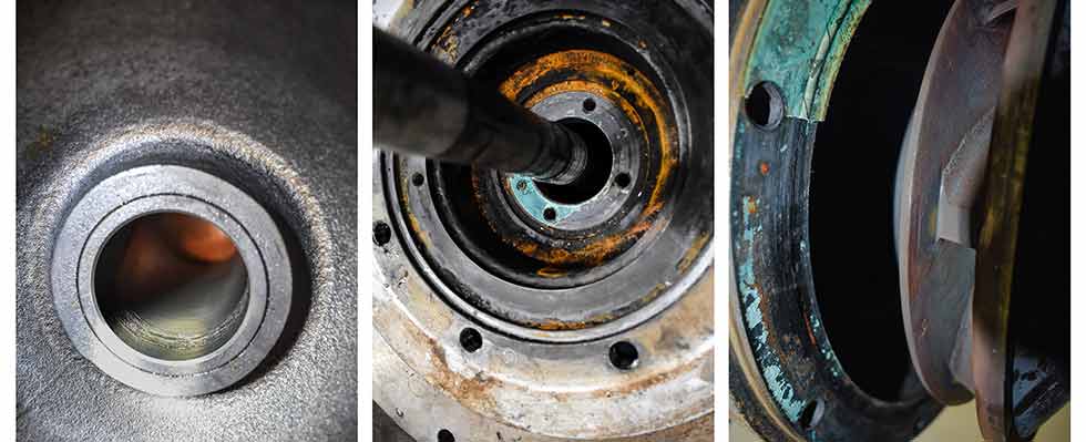
IMAGE 3: The damage could be found on the bearings, the shaft, impellers and more.
As the pump is de-energized, the hydraulic downthrust decreases due to reducing speeds during coast down. The large suction pressure acting on the shaft cross-sectional area can overcome the static rotor weight and hydraulic downthrust, causing the thrust to reverse and act in the upward direction.
An upthrust condition will cause shaft deformation as a compressive load is applied to a slender beam. This compressive load applied to the shaft will result in a first order mode shape wherein the deflection is greatest at the free end (first stage impeller location, Image 3). The live steam condensate pump inspection revealed heavy galling wear on the bearings with the largest degree of galling occurring in the first and second stages. This observation supports the conclusion that deformation of the shaft due to an upthrust condition contributed to bearing contact and shaft seizure (Image 4).
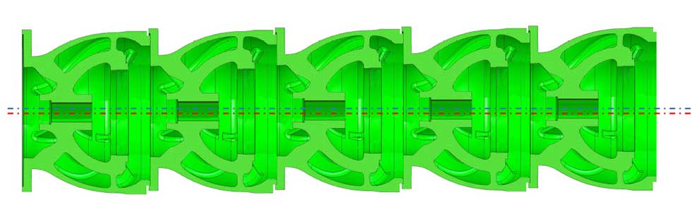
IMAGE 4: Stack-up of register fit tolerances leads to centerline offset when assembled in horizontal orientation
Because of the high galling propensity of the bearing material, any factor that increased the likelihood of contact between the shaft and bearing increased the probability of component galling and pump seizure. Just as the upthrust condition caused by the balanced impeller design made contact between the shaft and bearings more likely, the pump assembly resulted in noncenterline compatibility of the rotor and stator and also increased the probability of component contact.
One of the most important design goals in multistage pumps is to obtain centerline compatibility of all close-clearance mating components. This includes case wear rings, case bearings and line-shaft bearings. To satisfy this important requirement, proper assembly procedures must be employed.
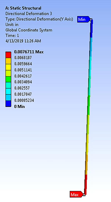
IMAGE 5: A model of the shaft deflection
Standard assembly of a multistage vertical element in a horizontal position will result in a centerline offset at each stage equal to the clearance in the male-to-female register fit due to gravity. The total offset can be as much as the fit-up tolerance times the number of mating components assembled. The original pump elements had been assembled in the horizontal orientation, causing maximum offset at the first stage, where the greatest damage occurred (Image 5).
Solutions
After analysis, the service provider worked in parallel with the end user to create a solution while providing an improved design and assembly process.
The design improvements included:
- removal of the back wear rings
- elimination the balance holes
- positive attachment of the impellers to the shaft via lock collars
- use of carbon graphite bearings in lieu of the 410 chrome steel bearings
The service provider assembled the element in its vertical assembly pit and followed it with its quality assurance/quality control (QA/QC) program. The new design and assembly improvements limited contact between the rotor and stator, while reducing galling at the bearings by providing a more suitable material.
The distress and delays to the commissioning of the alumina processing plant in the Middle East were a result of a nonconventional design configuration, incompatible materials and a less-than-optimal assembly procedure.
Many of these design choices, such as the use of balanced impellers, were made to reduce the first cost of equipment and remain competitive during the bid process.
For this reason, it is essential that a comprehensive specification is developed to ensure optimal design for critical components as uninformed choices can cost the plant in the long run with reduced equipment reliability and life.